

Description
Details
524WiFi™ Pulse · Pro Plus
Qualcomm IPQ5424 Marina tri-band Wi-Fi 7 router board
Build a tri-band Wi-Fi 7 platform with four radio paths on each band and six multi-gigabit copper ports. Two 10GbE interfaces support a fast wired backbone, while four 2.5GbE ports connect local network segments.
Quad-core Cortex-A55 at 1.8 GHz
2.4 / 5 / 6 GHz radio configuration
Model-specific RF integration
Board-specific software and test-image workflow
524WiFi™ Pro Plus — integration for your deployment

Our Pro Plus platform combines the selected hardware configuration with model-specific integration guidance and technical support. Plan the host software, wired topology, enclosure, cooling and power together, then validate the complete system for your intended workload.
524WiFi™ Signal Plus™ — match the complete RF system
Signal Plus™ brings antenna choice, operating band, polarization, connector type and cable loss together. Choose the RF harness for this board's actual connector count and radio allocation. Keep feed paths short and design antenna positions around the intended coverage area.
Where this platform fits
High-capacity access points, multi-gigabit gateways and wireless development systems with several wired network segments. Select the platform around the wired topology, client capabilities, available channels and enclosure. A multi-gigabit uplink gives the system room for several traffic flows; application throughput still depends on software, radio conditions and the rest of the network.
Technical specification
| Processor | Qualcomm IPQ5424 Marina; quad-core ARM Cortex-A55 at 1.8 GHz |
|---|---|
| Wireless generation | Wi-Fi 7 / IEEE 802.11be; MU-MIMO and OFDMA |
| Radio bands | 2.4 GHz + 5 GHz + 6 GHz |
| RF connectors | 12 U.FL connectors |
| Network interfaces | 2 x 10GbE RJ45 + 4 x 2.5GbE RJ45 |
| Memory interface | 4 GB DDR4, 32-bit interface |
| Flash | 32 MB NOR + 256 MB NAND |
| USB | USB 2.0 and USB 3.0 |
| Debug | 20-pin JTAG and 12-pin UART |
| Power | 12 V DC; 5 A supply design |
| Board power consumption | Up to 39.3 W, board only |
| Footprint | 215 x 180 mm; allow clearance for the supplied heatsink |
| Operating temperature | -15 to +70 degrees C |
| Storage temperature | -40 to +90 degrees C |
| Operating humidity | 5-95%, non-condensing |
| Compliance | REACH and RoHS according to the hardware documentation |
Each radio has its own configuration
| Band | Radio configuration | Maximum theoretical PHY rate |
|---|---|---|
| 2.4 GHz | 4x4 MU-MIMO | Up to 1376 Mb/s |
| 5 GHz | 4x4 MU-MIMO | Up to 8647 Mb/s |
| 6 GHz | 4x4 MU-MIMO | Up to 11530 Mb/s |
Supported channel widths: 20/40 MHz at 2.4 GHz; up to 240 MHz at 5 GHz; up to 320 MHz at 6 GHz. The listed PHY rates are theoretical radio link rates, not measured application throughput or a promised combined throughput. Channel availability, transmit power and 6 GHz operation follow the firmware and the regulatory rules of the installation country.
Software, QSDK and OpenWrt support
This platform uses a board-specific Qualcomm QSDK image with the matching Qualcomm radio drivers. Keep the bootloader, device tree, Ethernet configuration, calibration data and radio firmware together as one tested software set for the supplied board.
An OpenWrt port is available as a separately arranged software service. The porting service is chargeable. A test image can be supplied before ordering the source-code service, so you can validate the target application first. The delivered code is intended to reproduce the performance of the tested image. Contact our support to agree the image, source-code scope, licence terms and configuration for this exact assembly.
For development, record the image release, checksum, boot environment and board revision. Use UART for boot diagnostics and preserve calibration partitions before flashing. OpenWrt availability must be assessed for the complete board, including its radios and Ethernet interfaces, rather than assumed from a processor name alone.
Installation and commissioning
- Choose the enclosure, cooling and supply for the supplied board and its intended continuous load.
- Connect the 12 U.FL connectors with the correct connector type and antennas suitable for each band. Check the physical band labels before tightening or mating the RF harness.
- Commission Ethernet and, where fitted, the optical uplink before bringing up the wireless network.
- Flash the approved board-specific image, preserve calibration data and record the recovery procedure.
- Validate client connections and traffic in the intended environment, then retain the working configuration and image checksum.
Antennas and RF installation
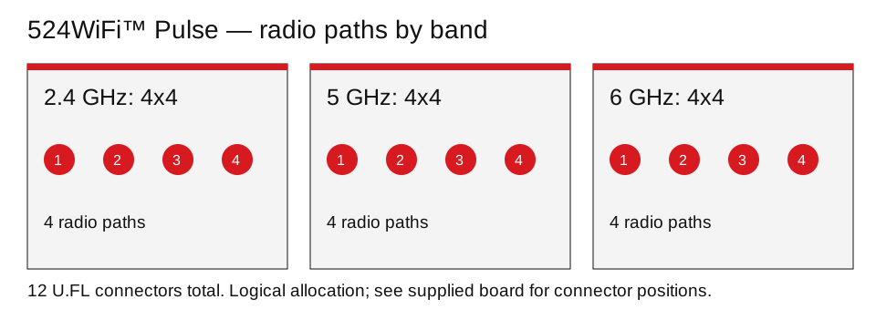
RF connector count describes the physical paths to be connected. MIMO describes the radio configuration on a particular band. Match both when selecting the antenna assembly; one total connector count does not describe all three radios. Choose frequency coverage, gain, polarization and cable loss for the planned deployment, and provide clearance from metalwork and nearby RF feeds.
Useful diagnostics
Record boot logs, negotiated Ethernet speed, channel width, client PHY rate and radio temperature during commissioning. Inspect each band separately when investigating coverage or throughput. Keep a known-good image and configuration so software changes can be compared against the same installation.
Frequently asked questions
Do all three radios have the same MIMO configuration?
Yes. This configuration uses four paths on each of the three bands: 4x4 at 2.4 GHz, 4x4 at 5 GHz and 4x4 at 6 GHz.
Can I use OpenWrt?
A board-specific port and test-image workflow are available by arrangement. Agree the chargeable porting and source-code service with our support after testing the supplied image.
What should I confirm when ordering?
Confirm the delivered memory and software configuration, antennas and RF harness, power supply, enclosure and any optical transceiver or expansion modules needed for your installation.
Configuration and ordering
Use the radio configuration, Ethernet and optical interfaces in this page to select the correct board.
Additional
Additional Information
| Brand | Wallys |
|---|---|
| firmware | No |
Tags
Reviews
Having a questiion ?? Contact us - info at 524wifi.com !!
-
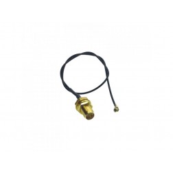 524WiFi WiFi 6 pigtail cable RF UltraMini U.FL plug to rSMA bulkhead 20cm, black cable
$3.49
524WiFi WiFi 6 pigtail cable RF UltraMini U.FL plug to rSMA bulkhead 20cm, black cable
$3.49 -
 524WiFi Hinged Blade WiFi 6/6E/7 Antenna tri band, 7dBi, RSMA male, 2.4 + 5 + 6 GHz triband, tuned, Linx
$7.99
524WiFi Hinged Blade WiFi 6/6E/7 Antenna tri band, 7dBi, RSMA male, 2.4 + 5 + 6 GHz triband, tuned, Linx
$7.99 -
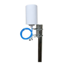 524WiFi™ Outdoor Wi-Fi 6E Omnidirectional Antenna, 4x4 MIMO, 2.4/5/6 GHz, 4/6 dBi, 4x RP-SMA Male, 3 m
$54.90
524WiFi™ Outdoor Wi-Fi 6E Omnidirectional Antenna, 4x4 MIMO, 2.4/5/6 GHz, 4/6 dBi, 4x RP-SMA Male, 3 m
$54.90