



524WiFi™ Pulse Industrial Mesh
Design a wireless backhaul that can follow the layout of your site. Combine fixed mesh nodes, roaming clients and a local management layer to carry control data, telemetry and video across production halls, yards and temporary work areas.
Start with application flows, then draw the topology
Start by drawing the boundary between the wireless system and everything it connects. List the devices that originate traffic, the services they need to reach and the locations where those services terminate. For example, a warehouse robot may exchange small control messages with a fleet manager, send status data to a local broker and upload camera clips to a server in another building. Each flow has its own direction, volume and tolerance for interruption. A design based on the combined average bitrate can still fail when several robots arrive at the same loading bay and upload at the same time.
Put these flows on a site plan before assigning channels. Mark the wired network handoffs, moving routes, elevated mounting points, metal partitions, work areas and places where equipment can be powered. Distinguish the longest route in metres from the busiest route in airtime. A short indoor path through shelving can be harder to sustain than a longer path across an open yard. A lightly used relay at the edge can be straightforward even when a nearby gateway is busy carrying traffic for the whole site.
Give each mesh relay an explicit role. A gateway node provides the transition to the wired or routed upstream network. A relay forwards between coverage areas. An access node serves local clients and may also relay backhaul traffic. A mobile client attaches equipment to an access cell. One enclosure can perform more than one role if the firmware and radio plan support it. Keeping the roles explicit makes it easier to measure the network and to decide where to add a node, a wired handoff or an additional radio.
A linear chain is useful along corridors, fences or roads, provided the deployment has an acceptable recovery strategy for a cut link. A branching topology lets one wired handoff serve several work areas. With two paths back to the wired network, check the independence of those paths at the RF, power and switching layers. For instance, two relays may use different mounting points while sharing the same crowded channel or power circuit. Draw both nominal and degraded paths and calculate the load each surviving segment would carry.
Design the data path first
In a self-organizing mesh, neighboring nodes form links and forward traffic across multiple hops. When the topology offers an alternative path, a node can reach the wired network through another neighbor. The firmware determines how paths are selected and how quickly the network converges. Map at least two physically distinct paths for critical areas and check that those paths do not share a single point of failure such as a power supply, a congested RF channel or a gateway.
The mesh platform described in the technical presentation forwards Ethernet traffic at Layer 2. For industrial network integration, verify VLAN handling, multicast and broadcast behavior, and the specific application traffic end to end. For CAN-based systems, plan the interface or gateway that maps fieldbus traffic onto the network. For PROFINET, validate the actual operating mode and timing with the controller and I/O devices used on site.
What a distributed Layer 2 network means for integration
The architecture described in the presentation behaves as a distributed Layer 2 forwarding system. Inside a supported Ethernet segment, that can preserve addressing and simplify integration when devices move among access cells. Start by documenting where each VLAN enters and leaves the mesh and where traffic is routed. Confirm that the bridge and upstream switches agree on the tagged and untagged traffic expected at every wired interface. Check that the management network remains reachable when access or backhaul segments are reconfigured.
Test unicast, broadcast and multicast separately. DHCP and ARP each need a working discovery path. IPv6 applications can depend on neighbor discovery, and industrial discovery or video applications may rely on multicast. Mesh broadcast optimization is useful when several relays would otherwise forward duplicate frames. Verify what happens when a device joins, when a receiver moves and when a relay restarts. Measure airtime during discovery and after the system settles. Where group traffic is substantial, confirm the forwarding and filtering behavior on the actual firmware.
With two wired entrances to the same Layer 2 segment, document how the installation handles redundant paths and loop prevention. Confirm the expected behavior when the first wired entrance recovers while the second is still forwarding. On a routed design, test the expected IP path and service discovery after a gateway change. The commissioning target is predictable forwarding with each intended gateway available and with each credible failure taken in isolation.
For industrial protocols, qualify the exact traffic and timing requirements. A controller discovering field devices by Ethernet will exercise different behavior from a machine sending status over TCP. Test a representative PROFINET controller and I/O device, including startup, cyclical traffic and recovery after a path change. A CAN or ISOBUS installation typically starts with a gateway or device interface that places the required data on Ethernet or IP. Verify the gateway's encapsulation, update rate and timeout behavior alongside the mesh. Use the application's own diagnostics to confirm successful cycles and recovery.
Separate roaming, forwarding and management
Fixed nodes forward traffic across the backhaul. Moving clients change their point of attachment as they travel between coverage cells. Design cell overlap along the actual route and test handovers at operating speed, under load and with the production client firmware. At each handover, measure packet loss and the longest traffic interruption alongside the time reported by the client.
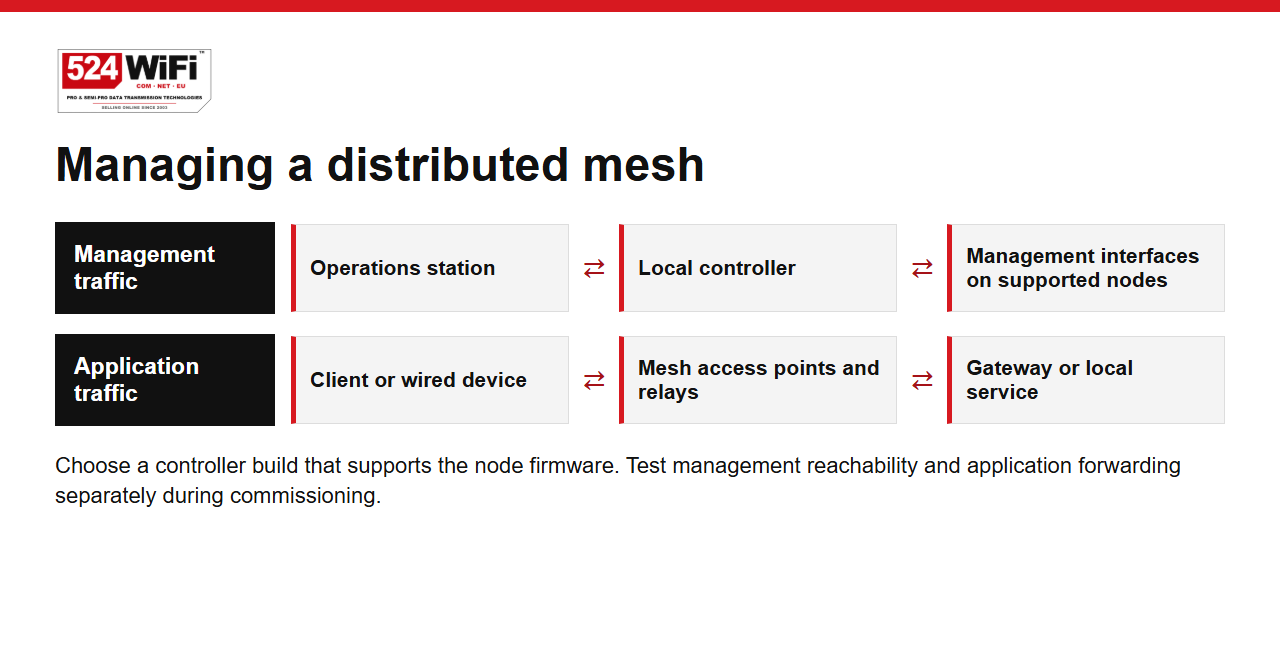
The mesh management layer gives engineers a place to inspect topology, links and node state. Use the controller documentation for topology visualization and commissioning. For a controller-based installation, confirm the supported node firmware and controller version together before specifying the system.
For centralized AP configuration and batch firmware maintenance, select a local controller for the AP models and firmware in your deployment.
Evaluate forwarding recovery and roaming independently
Moving between access points and rerouting mesh traffic are different events. In a client handover, the moving unit changes its point of attachment. In backhaul recovery, relay nodes change the forwarding path between the same endpoints. The events may coincide, for example when a mobile robot leaves the strongest cell just as a relay becomes unavailable. Recreate the events individually to establish a baseline, then exercise the combined case with the application running.
To evaluate roaming, instrument the moving unit and the receiving application with synchronized timestamps. Mark association changes on the machine's route, measure packet gaps and note any session reset. Repeat each transition in both directions and at realistic speeds. Test loaded and unloaded vehicles if a load can obstruct an antenna. A ping sequence helps correlate changes, while the control or video application reveals whether the interruption mattered operationally.
For forwarding recovery, interrupt one planned link and record when neighbors detect the change, when traffic first returns and when forwarding becomes stable. Check traffic in both directions. Repeat the test while restoring the failed path, since some systems will change routes again after restoration. Observe link and node state through the management interface while measuring the traffic from a separate endpoint. Decide which recovery thresholds are acceptable for each application before the test.
Install the controller on a reachable management segment and identify which access point models and firmware builds it manages. Start with a small set of representative nodes. Save the configuration, apply a shared setting, verify on the devices that the change landed and check that a node that was offline rejoins with an expected configuration. For batch firmware maintenance, stage an upgrade on one representative node and exercise its access, backhaul and management roles before scheduling a larger rollout. Retain a known-good configuration and a supported recovery path.
Plan radio capacity around concurrent traffic
Every transmission consumes airtime. A chain that reuses a channel across adjacent hops can contend for that same airtime at several points. With multiple radios, assign access and backhaul roles and plan channel reuse based on the RF survey. Include antenna placement, polarization, mounting height, overlap and the noise floor at each relay. The Pulse Pro Plus product range and Signal Plus™ antenna-system planning let you select fixed nodes, clients and antennas around those requirements.
Use QoS to prioritize control and telemetry over bulk transfers. Map application classes to the intended queues, check that classification survives each hop, and budget video traffic at its peak bitrate. Test latency, jitter and loss while multiple cameras are streaming, then repeat after interrupting a relay link. A cellular or satellite gateway extends reach. Size the uplink separately and budget its latency and bandwidth for applications that need to leave the site.
Build a radio plan for access and backhaul
Assign radios to roles before choosing transmit power. A practical design might put local devices on one radio and reserve another band for backhaul. On an appropriately configured tri-radio node, a third radio can serve a second backhaul direction or an additional access cell. The best arrangement depends on the hardware, the firmware's interface assignments, the channel plan and the sites where signals overlap. Confirm which combinations can operate concurrently and how neighboring nodes select their peers.
For the 2.4 + 5 + 6 GHz architecture, start by assessing which clients can use each band and which permitted channels are practical along the backhaul. The 2.4 GHz band can serve existing endpoints. The 5 and 6 GHz radios provide separate resources for dense links and backhaul where the deployment permits them. For a 2.4 + 5 + 5 GHz layout, assign the two 5 GHz radios to distinct roles and check separation between channels and antennas. Two nearby radios can still interfere when channel assignments, filtering or placement are poorly matched.
The supplier presentation shows two separate mesh AP configurations. Its 256 configuration combines 2.4, 5 and 6 GHz with 2.5GbE and Gigabit Ethernet with PoE. Its 255 configuration uses 2.4 GHz and two 5 GHz radios. Treat Ethernet speeds, PoE arrangements, enclosure options and optional positioning hardware as properties of the exact assembly ordered. The five linked Pulse products cover fixed tri-band infrastructure, mobile client radios and embedded integration. A three-radio mobile client and a three-radio fixed relay can serve different roles even when the band labels look similar.
Choose channel width for the actual RF environment. A wider channel gives a link more room when the spectrum is clean, while a narrower channel can make reuse easier in a crowded yard or manufacturing hall. Survey at both ends and at intermediate relay locations. Record the occupied channels, noise floor, received signal, link rate and retransmissions under load. A survey after hours captures the physical site. Repeat it during production to include neighboring radios, moving obstacles and the site's normal traffic.
Use the Signal Plus™ antenna-system planning approach to check the antenna type, orientation, placement and cable routing as a system. Directional antennas can concentrate coverage along a defined backhaul. Access cells serving moving equipment usually need a pattern that covers the full working route. Check what happens when the machine turns, parks next to metal stock or passes under a structure. Label ports and antenna cables so one replacement can be made without changing the intended radio assignment. Save the installed antenna and radio configuration with the topology drawing.
Engineer the uplink and QoS as separate budgets
Classify traffic by the behavior the application needs. Time-sensitive commands and telemetry generally need predictable delivery and a bounded interruption. Live video needs sustained capacity and can often adapt its encoding rate. Log uploads, map updates and maintenance transfers can run in a separate class with a rate cap or a schedule. Describe minimum and peak demand per source and multiply by the number of sources that can use the same bottleneck at once.
In a deployment with a managed gateway, document where each traffic class is identified and how markings carry through the system. An endpoint may mark packets with DSCP, a switch may use VLAN priority and the radios may map traffic to Wi-Fi access categories. Validate the mapping using captures and counters at representative hops. Then confirm the result under saturation. The useful outcome is that control and monitoring stay inside their thresholds while video and bulk traffic use the remaining capacity.
Instrument the busiest link and the gateway uplink independently. A healthy local backhaul can still feed a congested satellite or cellular service. Locate traffic that can terminate at a local recorder or server and send upstream only the streams and data needed off-site. Apply the uplink traffic policy at the point where contention occurs. Include variable latency and upload capacity in the field measurements.
For a temporary deployment, one satellite terminal, a cellular router or an available fibre drop can hand off an IP uplink to the mesh. Place the uplink where it can operate reliably and distribute connectivity from there through fixed relays. If another uplink is available, test gateway failover with active application sessions and record the effect of any address or routing change. Keep an on-site path for services that the local team needs during a WAN outage.
What the throughput tests measured
The platform supplier reports sustained 400 Mb/s at the last node of a ten-hop IPQ5018 mesh chain. The supplied diagram shows wired test endpoints and wireless hops between access points. Use this as a reference for that topology. For project sizing, record the radio and channel assignments, channel width, firmware build, RF conditions, traffic direction and concurrent load in your own test.
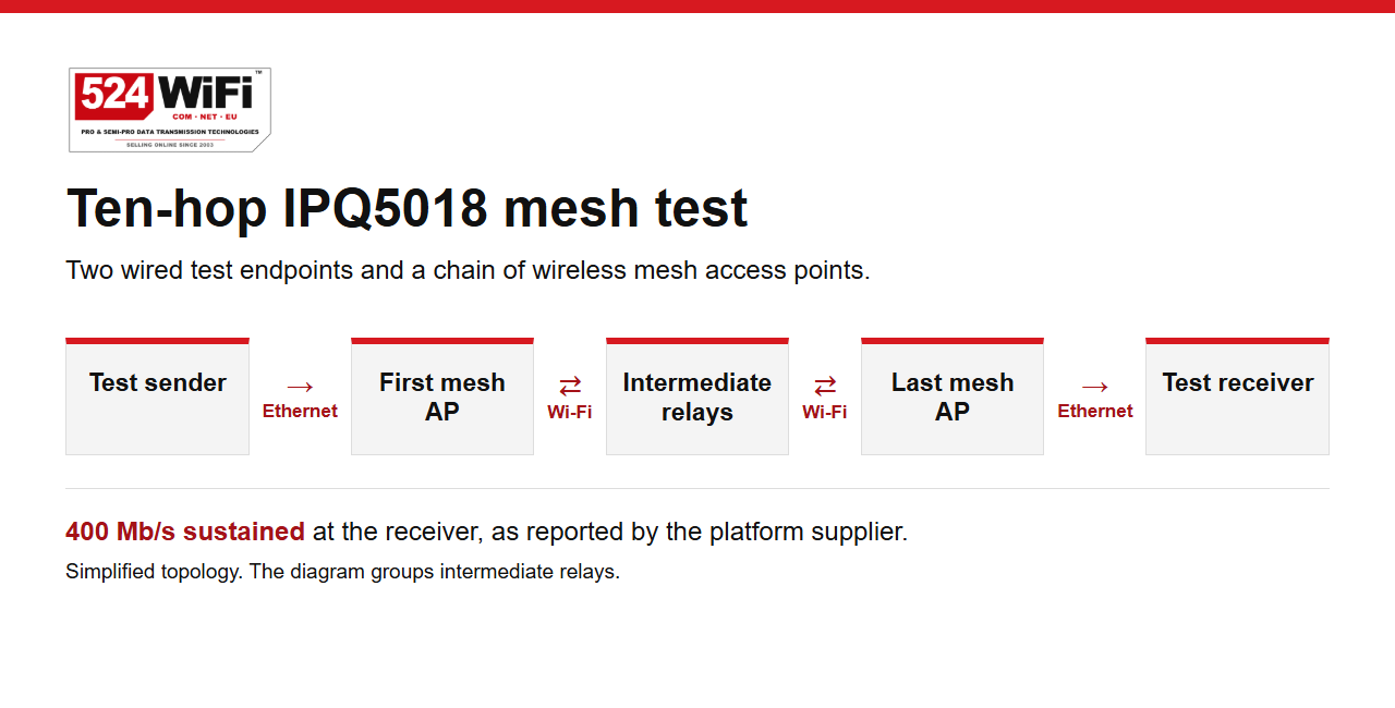
A separate three-node, two-hop setup used 5 and 6 GHz backhaul and achieved approximately 624–634 Mb/s aggregate with ten parallel iperf3 streams. The three-hop outdoor field test documents a four-node layout over approximately 730 metres. These setups give engineers reference points for different deployment layouts and traffic profiles.
Read the test numbers with their topology
The three published reference points answer different questions. The ten-hop chain shows what the supplier reports for sustained end-node throughput with its IPQ5018 mesh setup. The two-hop test shows aggregate throughput with parallel streams and 5 and 6 GHz backhaul. The outdoor four-node test adds a documented physical route and a third wireless hop. Use the matching reference when selecting a starting topology, then qualify the build against the loads and conditions of the actual project.
A useful test fixture has a fixed wired sender at the gateway and a wired receiver that can move from relay to relay. Keep a second receiver on the access network to exercise the client path at the same time. That gives three observations in one run: the contribution of each wireless hop, the effect of ordinary client traffic on the chain and the load at the gateway. Save a separate baseline with the receiver at the first relay. When the far end slows, compare the two baselines and inspect retries and queueing before moving antennas or changing the channel plan.
| Setup | Published observation | What to test on site |
|---|---|---|
| Ten-hop chain | Supplier reported sustained 400 Mb/s at the last node. | End-to-end throughput and degradation under concurrent traffic and relay failure. |
| Three nodes, two hops | Approximately 624–634 Mb/s aggregate across ten parallel streams. | Single-stream performance, aggregate capacity and latency at peak load. |
| Four-node field route | Three wireless hops over approximately 730 metres. | Actual route geometry, rates at each hop, interference and antenna alignment. |
For a comparable throughput run, start with wired endpoints that can independently exceed the target rate. Confirm the interface link speeds and TCP test direction. Use a single stream first, then add the same number of parallel streams that the reference uses. Record the test duration, reporting interval, average and lowest sustained interval. For video or telemetry, generate the intended packet sizes and rates as a second test. Collect application latency, jitter and loss with and without the competing traffic.
Repeat at each intermediate node and at the last node to isolate the segment where capacity changes. Record channel width, operating frequencies, firmware versions, active radios, antenna placement, retry counts and time of day. Keep the client count fixed for the baseline, then run a representative deployed load. After a path interruption, measure the recovered route using the same traffic profile. Store a topology diagram, configuration export and timestamped results together so the next team can reproduce the run.
Select the 524WiFi™ Pulse hardware by role
- Pulse M5018-2x2-TB-IN Pro Plus
- Fixed indoor mesh AP for factory floors and warehouses. Three 2×2 radios at 2.4, 5 and 6 GHz, 2.5GbE and Gigabit Ethernet with PoE.
- Pulse M5018-2x2-TB-OUT Pro Plus
- Fixed outdoor mesh AP for yard and campus links, with three 2×2 radios, 2.5GbE and Gigabit Ethernet with PoE. Plan the enclosure, antennas and permitted operating bands for the installation.
- Pulse R5018-2x2-2G5G-IN Pro Plus and Pulse R5018-2x2-2G5G5G-IN Pro Plus
- Dual-band and three-radio roaming client routers for Ethernet-equipped mobile assets such as AGVs and AMRs. Choose the radio layout to match the access cells and handover plan.
- Pulse B5018-2x2 Pro Plus
- Embedded IPQ5018 router board for engineers integrating the radio platform into their own enclosure and antenna system.
Translate the presentation into deployment scenarios
Industrial robots and logistics
Use fixed indoor mesh nodes to build coverage around the real movement patterns of AGVs, AMRs and automated carts. Equip mobile assets with a roaming client that matches the access design and connects their onboard equipment over Ethernet. Determine where several routes converge and test the sum of their camera and telemetry loads. Check stops, turning points, docking stations, transitions between buildings and areas with dense shelving. Commission both a normal mission and a recovery route with the operator's application in use.
Construction sites and outdoor work areas
Use fixed outdoor relays to connect temporary offices, remote cameras and changing work zones. Start with a serviceable mounting plan and a link map that can be revised as machinery and materials move. Check the longest path to the site gateway and the highest combined camera load. Give critical relays predictable access to power and a documented replacement location. Use the outdoor field test as a model for recording distances, node positions and per-hop measurements.
Fire and emergency response communications
A temporary network can distribute access from a satellite, cellular or wired handoff to teams operating around a site. Put a gateway where it can be powered and where the upstream service is usable. Extend from there with relays toward the incident workspace. Test local communications and the separate path to a remote command centre. Prioritize messaging, position and status updates, and monitor the impact of selected live video. Run the evaluation with the team responsible for operating the system, including setup, repositioning and recovery after a relay is removed.
Mobile cameras and heterogeneous inspection systems
The presentation describes trials with mobile aerial and ground platforms carrying simultaneous video and telemetry. The engineering pattern is to separate the flows by priority and measure their demand as vehicles change position. In a civil inspection project, start with the camera stream requirements, the number of simultaneous feeds and the position of the operator or recording station. Watch for brief loss of line of sight as a vehicle moves behind infrastructure. Keep the design and acceptance criteria specific to the equipment and site being commissioned.
The supplier's examples illustrate the difference between a high-capacity reference link and a loaded mobile system. Its mixed mobile case describes control and media flows sharing a network over multiple hops, with an expected 40–45 Mb/s within three hops for that scenario. Use such a figure as scenario context, then size your own streams against measurements taken with the planned number of platforms, traffic mix, link geometry and radios.
Commission for the worst working route
Begin with the most demanding path. On a production floor, drive the AGV through shifts in coverage with control and video running. On a construction site, test the gateway at the planned uplink location and check how moving machinery affects relay links. In a temporary emergency communications deployment, verify the path from each working area to the wired, cellular or satellite handoff. Test mobile inspection cameras along their working routes with the same traffic mix they will carry in service.
- Record the topology, firmware versions, channels, antenna locations and wired gateway paths.
- Measure throughput in both directions, application latency, jitter, loss and handover interruptions with the expected number of active clients.
- Disconnect a relay during the test. Measure how long operational traffic takes to recover on the alternate path.
- Repeat at the busiest time and at the coverage boundary. Use the results to set acceptance thresholds for each application.
Turn acceptance tests into an operating baseline
Before handing a site over, agree on a threshold for each required service. For a moving controller that might be the longest interruption it can tolerate. For video, it may be the minimum usable rate and the allowed duration of a quality reduction. For the management plane, verify that a technician can reach the controller and critical nodes from the intended management segment during normal operation and after a change in topology. Record the metric, the measurement method and the owner of the acceptance decision.
Make the site baseline practical to use during maintenance. Keep the per-node identity, enclosure, power source, antenna connections, channel assignment, firmware and management address in one inventory. Record the location of the wired demarcation and any gateway that encapsulates industrial traffic. Include the normal operating path and one observed degraded path for each critical service. Note the measured restoration time and any operator action required to restore a lost service.
Recheck the important paths after changes in the building, machinery, nearby wireless systems or application mix. A new row of racks can change an access cell and a new batch of cameras can change the gateway load. Compare new measurements with the recorded baseline at the same location under equivalent traffic. Update the topology and configuration records whenever a node or channel assignment moves. That gives the next change a measurable starting point and makes vendor test data a useful companion to the site's own evidence.